|
By Rono - 10 Years Ago
|
I'm trying to calculate the exact compression ratio for my blown stroker motor and found this calculator on-line; http://www.csgnetwork.com/compcalc.html
I have all the information needed to plug in the numbers, except for "Head Gasket Bore Diameter" I am not exactly sure what they mean and I don't have a set of Fel Pro gaskets to measure this dimension. Can anyone give me a number to plug in here? That is not a perfectly round area anyway so I am not exactly sure what they are looking for.
Also, there is no provision in this calculator for a relieved block. Is there a % reduction ( i.e. 1% or 5%) that can be subtracted from the calculated CR?
Thanks,
Rono
|
|
By aussiebill - 10 Years Ago
|
Rono (12/31/2015)
I'm trying to calculate the exact compression ratio for my blown stroker motor and found this calculator on-line; http://www.csgnetwork.com/compcalc.htmlI have all the information needed to plug in the numbers, except for "Head Gasket Bore Diameter" I am not exactly sure what they mean and I don't have a set of Fel Pro gaskets to measure this dimension. Can anyone give me a number to plug in here? That is not a perfectly round area anyway so I am not exactly sure what they are looking for. Also, there is no provision in this calculator for a relieved block. Is there a % reduction ( i.e. 1% or 5%) that can be subtracted from the calculated CR? Thanks, Rono
Ted knows that general number for h/gskt bore displacement figure, i dont think the relief amount is going to make a big difference regardless as the whole calculation is a general one.
|
|
By Rono - 10 Years Ago
|
Thanks Bill;
You Blokes had an impressive fireworks display for the New Year...saw it on the Tele.
Happy New Year!
Rono
|
|
By miker - 10 Years Ago
|
Ron,
This is a bit off topic, but it's the calculator I found when I was rebuilding the motor and trying to select the cam. There's a bunch of dynamic calculators out there, and they don't all agree. This one's interesting in that it's an add on to static ratio.
I have no idea how this relates in practice to a blown application, but I found it interesting looking at different cams and rod lengths.
https://www.uempistons.com/index.php?main_page=calculators&type=comp&zenid=8e9027fc60bbc5227c417444b739f709
|
|
By NoShortcuts - 10 Years Ago
|
Rono. Hmmmm...
What your formula is trying to do is determine the total effective volume of the combustion chamber you're using on your SC engine. The last I knew, Rono, you're using a set of 5750-471 y-block cylinder heads. Per JM's cylinder head chart, 5750-471 heads have 82 cc combustion chamber volumes.
NEXT, you're going to ADD to the 82cc combustion chamber volume the EFFECTIVE VOLUME of the cylinder head combustion chamber gasket areas that you are using with the brand of gaskets that you used when you assembled your engine.
Remember that the y-block has an i-r-r-e-g-u-l-a-r cylinder head combustion chamber perimeter shape AND that different gasket suppliers have varied their cylinder head gasket 'fire ring' contours slightly and consequently their actual perimeter gasket 'fire ring' lengths slightly. Sooo... this is WHERE Ted Eaton has helped us generously.
EXPLANATION: Ted Eaton has calculated the cylinder head combustion chamber gasket volumes by actually measuring the perimeter length of each companies' combustion chamber gasket 'fire ring' AND also measuring the thickness of that same gasket material after compression caused by torquing the cylinder head bolts!
Ted's measurement has permitted him to calculate each of the various individual gasket manufacturer's effective combustion chamber 'fire ring' bordered combustion areas. This combustion chamber gasket area has the effect of adding to the size of the actual cylinder head combustion chamber area. In summary, the gasket area volume varies depending upon the gasket manufacturer's 'fire ring' dimensional length and how much that manufacturer's gasket material compresses when torqued down.
So, using Ted's cylinder head gasket chart, locate the gasket manufacturer and the particular gasket type from them that you're using. Ted's chart indicates the perimeter length of the fire ring and the actual compressed thickness of the particular manufacturer's gasket. Going across, Ted's chart also gives the cc volume that using that manufacturer's gasket will effectively add to the volume of your combustion chamber. TG for Ted! 
Click on the link below to see Ted's cylinder head gasket chart listing head gasket combustion chamber volumes
http://www.eatonbalancing.com/blog/2012/06/30/head-gasket-volume-calculation/
Adding the gasket area volume to the combustion chamber volume gives you the effective combustion chamber volume above the piston. IF your relief work on the deck of the block is 'significant', you'll need to measure it by forming a dam around it and using a fluid to determine the volume of material removed in ccs. This figure would be added to the above calculation. The same would need to be done if you had used dished pistons to lower the compression ratio because of using small combustion chamber heads when using a blower or supercharger.
Hope this helps.
|
|
By NoShortcuts - 10 Years Ago
|
Rono. Me thinks that you'll come-up with the answer you're looking for if you use their formula, BUT only enter your numbers for cylinder bore, piston stroke, and your determined number for total effective combustion chamber volume.
Assuming you zero decked your engine block...
Total effective combustion chamber volume with your y-block is
combustion chamber volume + cylinder head gasket combustion chamber volume + cylinder block deck relief volume
IF you did not zero deck your block, you have to take the in-the-hole piston depth (in thousands) and calculate the volume above the piston diameter using your cylinder bore size. After doing that, add that additional number to the above 'total effective combustion chamber volume' to be more accurate.
Happy New Year!
|
|
By Rono - 10 Years Ago
|
Charlie;
Thanks for all your help with this!
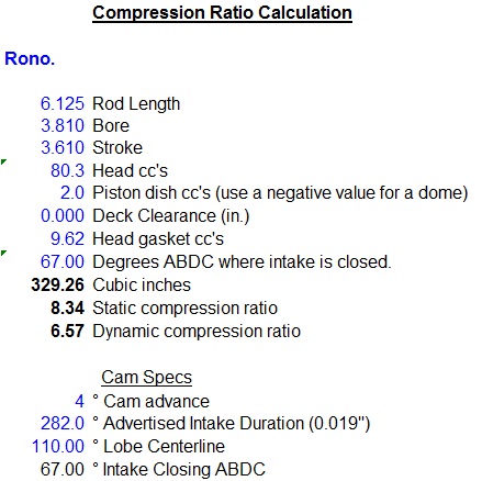
Well, I crunched the numbers. I'll provide them below and maybe you can double check my result;
Bore Size - 3.810
Piston Stroke Length - 3.610"
* Head Gasket Bore Diameter - 12.95"
* Ted's formula for the Fel-Pro Perma torque uses "sealing ring distance in inches" (12.95") which is what the formula I used is asking for I think.
Compressed head gasket thickness - 0.044"
*Combustion Chamber Volume - 82 cc
* I used the 82 cc for the 471 heads, but that would be for stock, un-milled heads, correct? My heads are milled 0.010" which would reduce the volume right? May
maybe 75cc would be a more realistic volume #.
Piston Dome Volume - 0 (I had john Mummert cut the domes flat on my pistons)
Piston Deck Clearance - I did zero deck the block (it actually came out to 0.002" below deck)
The calculator program uses Java Script which my old lap top doesn't have, but my wife input the numbers and came up with a 4.8:1 CR and that is without considering the block relief.
We re-ran the numbers using a Combustion Chamber Volume of 75cc (for milled heads) and got a CR of 4.95:1
Unless I'm missing something, this is pretty low compression which should allow me to run a little higher boost without detonation using pump gas.
The reason I am going through all this is because I unfortunately will be selling my complete blower set-up. I just cannot fit it within the narrow front part of the engine bay in my 37 coupe. The bracket interferes with the outer fender. I have been talking quite a bit with Y-Bloke and will be going with his blower intake and a 4-71 blower. I'll be posting pictures in the classified section of our forum next month with a full description and price. I hate to do it, but it is what it is.
Rono
|
|
By NoShortcuts - 10 Years Ago
|
Rono: Just beginning to work with the info you've provided...
I. Volume of the combustion chambers of your cylinder heads after milling...
The 'pads' on y-block cylinder heads when fresh from Ford were suppose to be 1.000 thick (theoretically)
IF they weren't previously re-surfaced until you had them milled, they should now measure 0.990 (theoretically)
Ted's website has an article with a chart indicating how much cut it takes to remove 1 cc of volume from the combustion chamber of different versions of y-block heads
My quick read on Ted's chart is that on the 471 heads, a .0.010 cut would remove (almost) ~2 cc of combustion chamber volume. (close theoretical calcuation)
JM's chart is an indicator of what Ford was trying to produce combustion chamber volume-wise. Those who do engine blue printing will tell you that chamber volumes on production heads DO vary, BUT let's not get too clinical about this...
IF your production 471 heads were 82 cc, let's say that they're 80 ccs now after milling .010 off of them.
Click the link below to see Ted's article and chart on y-block head milling to adjust combustion chamber volume...
http://www.eatonbalancing.com/blog/2013/01/30/cylinder-head-milling-for-a-1cc-reduction/
Okay? I'll be back...
|
|
By gyrogary - 10 Years Ago
|
Rono that 12.95" dimension is the circumference and needs to be divided by pi to give you a
gasket bore of 4.122"
I get 8.528:1 compression or there abouts.
|
|
By NoShortcuts - 9 Years Ago
|
Rono. Quite sure that I've got the correct answer based upon what I've done with using your information and Ted's with their website calculator.
- I presently have not been able to post a copied and pasted picture of their data page entry form with my data inserted on it using our Forum entry page
- My hope was to add footnotes for some entry numbers to help explain how you went astray in using Ted's information.
Here's the short of what I did:
Bore / Stroke Designation Type - entry #1 = Inches
Enter Cylinder Bore Size - entered 3.810
Enter Piston Stroke Length - entered 3.610
Enter Head Gasket Bore Diameter - entered 0.000 [reason: using Ted's data here will not work for calculation of y-block combustion chamber irreg. gasket shape]
Enter Compressed Head Gasket Thickness - entered 0.000 [reason: same as above... program calculation will not work for y-block cyl. hd. comb. chamber gasket]
Enter (TOTAL) (EFFECTIVE) Combustion Chamber Volume In CCs - entered 89.62 [471's chamber volume 80 cc + 9.66 cc FelPro gasket chamber volume]
Entered Piston Dome Volume In CCs - entered 0.000 - [reason - flat top pistons per JM's machining]
Enter Piston Deck Clearance - entered 0.000 - [reason - block was all but zero decked! pistons grow with heat -are probably flush with deck in norm. operation!]
I clicked the 'Calculate CR' [Compression Ratio] button at the bottom of the data entry area...
Very Bottom of Data Page...
Calculated Engine Compression Ratio - Answer - 8.52563590200843 : 1
Total (EFFECTIVE) Displacement Volume - 89.62 cc [this number is 471 hd. comb. chamber vol. + FelPro cyl. hd. gasket combust. chamber volume per Ted]
What has NOT been valued in doing this computation using this Internet calculator?
- we did not include a calculation of the volume of material you removed from the block deck in doing relieving work...
- we did not include ANY cc allowance for the space in each cylinder above the top piston ring and the block deck... Ted will tell you this is of measure, BUT...
IF you follow what I've done, GooD! IF you don't, I'll go at it in explaining it another way, OR more completely...
The reason Ted did all of his gasket calculations is that no existing computer program could process hd. gasket combustion chamber information and come-up with the cc volume for the area inside the fire ring area on the different y-block manufacturers' cylinder head gaskets.
Again, THANK YOU, Ted Eaton!
|
|
By NoShortcuts - 9 Years Ago
|
gyrogary (1/1/2016)
Rono that 12.95" dimension is the circumference and needs to be divided by pi to give you a gasket bore of 4.122" I get 8.528:1 compression or there abouts.
YES, Gary! Your approach of using the 'fire ring' measured length (per Ted) as the circumference of a circle to work backwards and transpose it into a bore diameter would permit using the existing Internet computer program. Good Thinking!
I believe that we've both come-up with statistically the same compression ratio! Thanks for coming in on this! We've verified each others answers by arriving at them different ways!
Ron, I trust you're happy to get this worked through!?!?
Best Wishes for a Happy and Healthy New Year to all of you!
|
|
By Rono - 9 Years Ago
|
Charlie;
Thanks very much for re-calculating the CR for me. Quite a difference from my CR number, but I'm glad it is more accurate than what I came up with. I don't have an accurate way now to calculate the volume of the amount of material I removed when I relieved the block because it is all assembled. I can say that the depth of the reliefs were 1/2 the distance from the top of the piston to the top of the top ring or 1/8" deep (from top of top ring to top of piston was 1/4"). So, I think it would be safe to say that my CR would be between 8.0 and 8.5. Consequently, to keep my EFFECTIVE compression ratio (static compression ratio plus amount of supercharger boost) below 12.1 psi on pump gas (i.e. 92 octane), I need to keep the boost pressure at about 6 psi (not 7 psi as I was planning). You can run more boost if you increase the octane rating, but that can get expensive. Now I can choose my blower pulleys with more confidence.
Thanks Again!
Rono
|
|
By NoShortcuts - 9 Years Ago
|
Rono. From your description, methinks you and I have done the same version of Ford y block relieving only at different times.
In moving to a 4-71 type SC, do you need to consider swapping cranks? IF swapping to a forged crank has merit, I'll help you do it. Frank Rice and John 'The Hoosier Hurricane' have both mention snout issues with the cast cranks relative to blower drives. It would seem that the Roots type blower would be harder on the crank snout than the vane style you had. This is not my area of knowing a lot about what I'm bringing up. Point is, IF you need assistance in gettin' her done, we're both only going this way once. I want to see you do it the way you want to! Keep me in mind.
Regards,
|
|
By Rono - 9 Years Ago
|
Thanks Charlie. I've read about the possible cast crank issue, but I need to block that out of my mind right now. Way too much time and money to consider that at this point of the coupe build.. I need to get that car done! I don't plan on track racing the car and I don't think I'll ever hit 6K RPM on the street, maybe only on the dyno. So, I need to take my chances and stick with the offset ground cast crank for now and hope for the best! I do appreciate the offer though.
HAPPY NEW YEAR!
Rono
|
|
By Ted - 9 Years Ago
|
|
Rono (12/31/2015)
.....Also, there is no provision in this calculator for a relieved block. Is there a % reduction ( i.e. 1% or 5%) that can be subtracted from the calculated CR?
One method for determining the volume of a cylinder wall valve relief is to simply mold a piece of clay that fits the relief and then measure the amount of fluid that piece of clay displaces in a graduated buret. A large relief would be in the neighborhood of two cc’s.
Until you actually cc the heads, you don’t know what you have. As a general rule, they tend to be larger than published values versus being smaller. It will also be to your advantage to cc all the combustion chambers as the heads can potentially be larger at one end versus the other. In these cases, the heads can be angle milled from end to end in which to equalize the combustion chambers.
I have an Excel spreadsheet I use for both static and dynamic compression ratio calculations. This particular spread sheet does not take into account the space between the top ring and the top of the piston. I simply added 2 cc’s for the cylinder wall valve relief in the spot for ‘Piston Dish’. That same estimated value could have been added to the head cc number though and achieved the same result. Just compare my inputted values to yours and see how they compare. If you'd like a copy of the spreadsheet, just email me directly.
|
|
By pegleg - 9 Years Ago
|
Ted,
Does your Formula, using the cam specs, simply figure the actual volumes left at the valve opening/ closing? The reason I'm asking is that it seems to me that the actual volumes of the chamber would be affected by air flow efficiency in and out. In other words there has to be a difference in the totals between good and bad ports. Also the rates of fill at higher RPM would be less than at lower speeds. Max fill probably happens at the Maximum torque RPM.
|
|
By Ted - 9 Years Ago
|
pegleg (1/1/2016)
Ted, Does your Formula, using the cam specs, simply figure the actual volumes left at the valve opening/ closing? The reason I'm asking is that it seems to me that the actual volumes of the chamber would be affected by air flow efficiency in and out. In other words there has to be a difference in the totals between good and bad ports. Also the rates of fill at higher RPM would be less than at lower speeds. Max fill probably happens at the Maximum torque RPM.
Frank. While air density, port flows, atmospheric conditions, etc. are all players in calculating engine performance, that’s simply too many variables to make some realistic numbers that I can use for the everyday engine builds. My dynamic compression ratios simply calculate the cylinder volume at the point of the intake valve closing. A cylinder does not actually start making compression until the intake valve closes which in turn allows the spreadsheet DCR numbers to be good indicators for building an engine around a specific octane fuel. Beyond the values needed for the static compression ratio, all that’s needed for the DCR on my end is the intake closing event and the connecting rod length. If the camshaft is a symmetrical grind, then the intake closing event can be mathematically derived by simply knowing the advertised duration, the lobe centerline, and the number of degrees the camshaft is advanced or retarded.
|
|
By pegleg - 9 Years Ago
|
Ted
Kinda figured that.
|
|
By Cliff - 9 Years Ago
|
|
Rono, I had Bryant do the crank that is in my Bird now, they heat treated it when I told him that it was going to be supercharged, it has a McCulloch / Paxton hybrid supercharger (VS57 front end, SN2000 back end), it puts 10 lbs in the manifold, I used a 312 cast crank, most guys say you can not heat treat a cast crank however mine is and has about 10,000 miles on it now, also one of the engines I am building for my supercomp car will use a cast crank (3.35 stroke), steel cranks are heavy and don't have center counter weights.
|
|
By Rono - 9 Years Ago
|
Cliff;
Can you give me any contact information on "Bryant". I'm thinking that when the new aftermarket 312 cranks become available this spring, I may just buy one and send it off to them for heat treatment. I can't pull my motor apart now, I need to get the car further along. About what did that cost? Do they heat treat the entire crank or just up to the first bearing?
Thanks,
Rono
|
|
By Cliff - 9 Years Ago
|
|
Hi, Bryant only makes new cranks now (did mine a while ago), however any crank grinding shop can get it heat treated, Scat should able to do this, the entire crank is treated, some say it makes it brittle, I do not find this to be the case, I am having a crank done in a few weeks and was quoted $100.00 by Castillo's Crankshafts Specialist Inc (714 523 0321) in La Mirada CA
|
|
By Rono - 9 Years Ago
|
Thanks Cliff for the info. So if I was to buy a new SCAT 312 crank this spring (as a back-up for my stroker crank if it fails) wouldn't it need to be offset ground before being heat treated?
Rono
|
|
By Cliff - 9 Years Ago
|
Yes, I finish all work on the crank (grinding, balancing) before heat treatment, however there are a lot of people that claim that heat treatment of a cast crank does no good, Sonny Bryant was the one that recommend that it be done to my crankshaft.
|
|
By NoShortcuts - 9 Years Ago
|
Cliff. I'm surprised that ALL grinding and finishing work is done before the heat treating process with cast crankshafts.
In some production work I'm familiar with, my understanding is that the heat treating can be a wild card with parts 'growing' (!) or otherwise distorting during the process... Perhaps this is not a problem with iron castings... like a crankshaft.
Cliff, would you know if the heat treating you have done is 'through' heat treating or 'surface only' heat treating?
Thanks for any clarification you can provide on this. Appreciated!
Regards,
|
|
By Cliff - 9 Years Ago
|
Hi Charlie, I don't know what kind of heat treatment they do, however I know after heating the crank it is straighten and polished, the reason I do all work before heat treatment is the man balancing the rotating parts did not like to weld (add weight) or drill (remove weight) on a heat treated crank.
|
|
By charliemccraney - 9 Years Ago
|
The Scat crank will be forged so you don't have to consider cast crank issues.
|
|
By Rono - 9 Years Ago
|
Wow...I didn't know that . Will John M be able to offset grind the 312 SCAT cranks for stroker cranks?
Rono
|
|
By charliemccraney - 9 Years Ago
|
I think that will depend on the location and orientation of the oiling holes. If that is favorable, then I don't know of a reason that it cannot be offset ground like any other crank.
It will not exactly be a 312 crank. It will have 312 stroke with 292 mains.
More info:
http://forums.y-blocksforever.com/Topic118400.aspx
|