Hey there y-block32deuce - sorry for the delay in replying about the distributor type. Mine is the version produced right after '56 (fly weights in the base) with the circular grooves cast in the shaft housing and bushings in the fly weights - the later bodies were "three lobed" like a sixties or seventies distributor. The later version will take a set of guts from a seventies Duraspark II and screw together in a few minutes - Holun has one in his outfit. The upper rotor, stator, and reluctor go right in there - get a cheapo donor off ebay (or down at the salvage yard) and go.
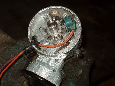
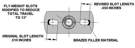
My earlier version was a different animal - the upper rotor has to have the point cam removed and it then has to be turned down to fit the seventies reluctor. We also did a little hot rodding mod to the flyweight slots to get the right spark advance curve. I made a print of the machining required to fit the reluctor - send me a PM with an address and I'l send a pdf file.

Once you have a distributor with the Ford stator and reluctor assembled - it will operate from a Ford Duraspark II box or with a MSD patch cord from an MSD "red box". Holun put a copy of the wiring schematic on his own site - its on a thread from last year, try a search of this forum. I put the later large diameter cap and rotor on my outfit - with the male plug terminals - it fits with a four barrel intake. I don't think you absolutely have to do this - but the wider terminal spacing is what Ford came up with for their electronic systems.
When I was trying to get this figured out I ran across several guys experienced in troubleshooting the Ford system - trying to decide for myself whether it was going to have problems of its own - and no better than the aftermarket stuff. The Ford control box hates heat - there were a considerable number of failures of boxes that were (factory) mounted directly adjacent to an exhaust manifold (don't). The boxes don't like low voltage - make sure it has a good solid full voltage source and decent wiring. I put both the coil and control voltage leads on a 30 amp relay operated by the ignition switch. Don't turn on the ignition and then let it fry without starting the engine (another reason I've got mine on a plug-in relay). The ground for the control box (black wire) goes all the way back to the distributor and gets screwed down to the distributor body at the stator plate. Then the body is (hopefully) grounded to the block through its base or clamp. What I understand is - this didn't work well and there were many service difficulties because of poor grounding. Using the distributor body for ground was OK for the points - but not always OK for the electronics.
This is where the common thread occurs with the Pertronix failures (I think). I've got one for my '56 tach drive distributor (now stored away). The instructions don't say diddly about the required ground to make the system work. On the points set-up you remove - there is a finely braided little ground jumper from the pivoting point plate to the distributor body so that the points can ground the coil when they close. When the Pertronix transistor tries to do the same thing (its mounted on the pivoting advance plate) - if the jumper is gone - it has to do so through the plate pivot. Some work - some don't - and some just screw up occasionally. I believe that the Pertronix system needs a grounding wire that attaches to the pivoting point plate and exits the distributor body to be fastened directly to the engine block.

Steve Metzger Tucson, Arizona