|
Author
|
Message
|
|
charliemccraney
|
|
|
Group: Moderators
Last Active: 2 days ago
Posts: 6.1K,
Visits: 442.9K
|
This is on the back burner for the moment because I've now started on projects which are actually on the drawing board for this year. I got some books about Geometry and Trigonometry to refresh my memory.
Lawrenceville, GA
|
|
|
|
|
charliemccraney
|
|
|
Group: Moderators
Last Active: 2 days ago
Posts: 6.1K,
Visits: 442.9K
|
Getting warmer. This is a hypothetical tube for #8. 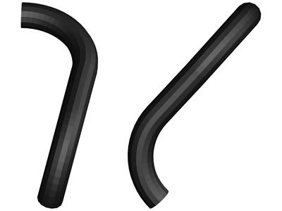 I think I find it easier to visualize the tube from the bottom up. I say I think because I'm still having trouble connecting point a to b. But it seems to be the right track because the arcs and line segments were calculated completely on paper and, as you can see, they seem to have lined up very well. If I didn't have to work tomorrow, I'd stay up a few more hours - or maybe all night trying to figure out where I am going wrong. Oh, I just realized one mistake.
Lawrenceville, GA
|
|
|
|
|
charliemccraney
|
|
|
Group: Moderators
Last Active: 2 days ago
Posts: 6.1K,
Visits: 442.9K
|
I made some progress today. All it took was some freshening up on lines tangent to arcs and circles. Combine that with the Pythagorean theorem and the law of sines and I figured out a part of my problem! Now to figure out what to do about the lower bend (which is not in this picture). But now it is time to sleep. 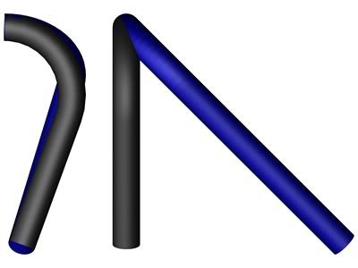 If anyone wants to know how to calculate the adjustment, just ask. I'm too tired to explain it now.
Lawrenceville, GA
|
|
|
|
|
glrbird
|
|
|
Group: Forum Members
Last Active: 7 Months Ago
Posts: 616,
Visits: 7.1K
|
I don't know if this will help you, but www.headersbyed.com has information on his theory and header parts for sale.
Gary Ryan San Antonio.TX.
|
|
|
|
|
charliemccraney
|
|
|
Group: Moderators
Last Active: 2 days ago
Posts: 6.1K,
Visits: 442.9K
|
Here is my problem. As the header tube is rotated, the required angle of the header tube coming out of the flange changes and the angle of the lower bend changes. I'm not sure how to account for this mathematically. I'm sure I know how, if I can just remember. Trig and geometry was always easy for me. I just don't remember much of it. I want the lower bend to point straight back and for the tubes to be parallel when viewed from the front. I'm sure I can get this by trial and error but if someone can tell me (hopefully remind me) what the correct approach is to figure it mathematically, it will be appreciated. The left is as if you are looking from the front of the engine. The right is as if you were looking from the side - the driver's side in this case. 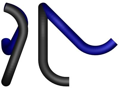 Doug T (3/16/2010)
This works, I have done it, but it does take time.I was a bit slow for some reason. You were implying that the process described above is what you did for your bird's headers. Those are some nice headers, too. I looked at them for a while at Columbus and took pictures for my own studies. I had no idea you made them. I guess I should talk more, huh?
Lawrenceville, GA
|
|
|
|
|
charliemccraney
|
|
|
Group: Moderators
Last Active: 2 days ago
Posts: 6.1K,
Visits: 442.9K
|
Oooh, maybe I should upgrade. http://www.youtube.com/watch?v=xOP69zhtuBYI'm operating on version 9.5. They're up to 16 now!
Lawrenceville, GA
|
|
|
|
|
charliemccraney
|
|
|
Group: Moderators
Last Active: 2 days ago
Posts: 6.1K,
Visits: 442.9K
|
It is the fact that the header pipes are not parallel that makes it more difficult than it seems at 1st glance. I've established points a and b for the tubes, one being at the header flange and one at the collector. That is pretty straight forward. It's the area in between that gets tricky. I'll make some illustrations tomorrow and you'll see what I mean. Making tubes is pretty easy. The way I do it is to first make a 3d multi-line which consists of arcs and straight lines. Once the multi-line is figured out I draw a circle of some diameter (or a square, or hexagon, or any irregularly shaped 2d object) and extrude the circle, using the multi-line as the path. I'm experimenting with a 2d layout scheme to assist with determining the proper angles but it's not completely fool proof because the angles have to be taken into account. I'd recommend TurboCad to anyone in our hobby as it is not as expensive as AutoCad but it seems to be able to do almost anything and it's easy to use. A lot of graphic designers seem to use it and some of that work is amazing. http://forums.turbocad.com/index.php/topic,2440.0.htmlhttp://forums.turbocad.com/index.php/topic,2809.0.htmlhttp://forums.turbocad.com/index.php?board=3.0
Lawrenceville, GA
|
|
|
|
|
Doug T
|
|
|
Group: Forum Members
Last Active: 3 Months Ago
Posts: 563,
Visits: 2.6K
|
Hi Charlie, I have had only a little CAD training but from what I understand the problem is defining starting and end points of each segment of the tubes because each arc or straight segment must be attached to the one before itself. The CAD program should be able to handle this but you have to know where you want the pipe to go next. When one is designing a chemical plant pipe rack this is fairly easy because those designers seem to run pipes parallel to the X Y & Z axes. But in your case you will want to run at diagonals in free space joining two or more segments. This depends on knowing where the interferences are which will also include the other 3 pipes.
Doug T The Highlands, Louisville, Ky. 
|
|
|
|
|
charliemccraney
|
|
|
Group: Moderators
Last Active: 2 days ago
Posts: 6.1K,
Visits: 442.9K
|
It is 3d CAD. I use TurboCad Pro. At this point I'm just trying to figure out how to model a hypothetical header so I can learn how to solve any of the problems that may arise within the software. I'll make some illustrations later to show specifically what is troubling me. So far, I haven't really had trouble with the software more a lack of mathematical knowledge.
Lawrenceville, GA
|
|
|
|
|
Doug T
|
|
|
Group: Forum Members
Last Active: 3 Months Ago
Posts: 563,
Visits: 2.6K
|
Hi Charlie, If you are modelling using a 3D CAD program then obviously you will have to draw the engine compartment in 3D to find interferences. You then find your metal bender or U bends source to find out the bend radius of the available in the sizes you want. Then proceed to use the CAD program to lay out the pipes with those radii. I don't think this will be really reliable without something really good like AUTOCAD. If you are asking for a (simple?) way to fit headers to your specific situation without CAD work then you need to get some dummy wooden flanges and some 1/8 or 3/16 dia metal rods. The rods should be the length that you want the header tubes to be. Lay out circumfrences at the radii that are available for the U bends on something like cardboard including on the cardboard angles at 5 or 10 deg intervals around the circ. Drill the dummy flanges for your rods and mount them on the engine Then stick the rod into the flange and start to bend the wire to go where you want to end up. As you do this, continue to remove the rod and conform the bend to the radius on the cardboard noting how far around you bend it. Once you have done this for one tube continue to do it for the rest of the tubes. When this is done make four beads that are the outside dia of the tube you want to use and slide them over each tube to be sure that everything cleared by the tubes. Note that you can play around with this system to fine tune clearance for spark plugs oil filters etc. The rods are stiff enough to hold their shape when removing and if there is a commercial bender involved you can take the wires to him and get the tubes bent. If you are going to cut and weld U tubes you will know what you need to order and how to cut them when welding together. This works, I have done it, but it does take time. but it does take time.
Doug T The Highlands, Louisville, Ky.
|
|
|
|