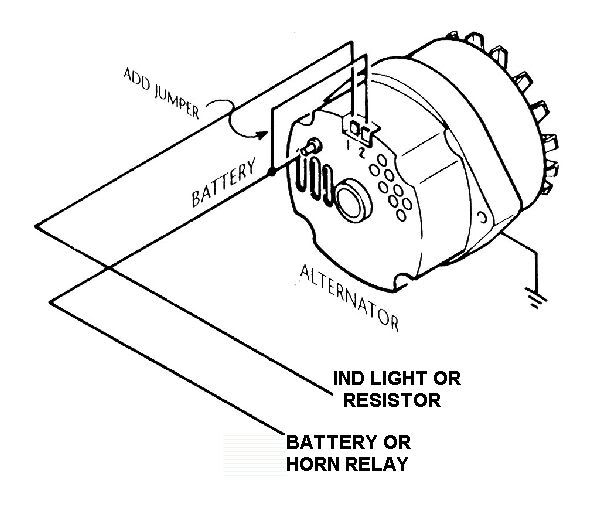
This is the necessary wiring info for a GM "S12" alternator - that has the
three wire connection. One of the wires is "jumpered" directly to the output terminal so that it becomes a "two wire" system. Using the three wire set-up gives you the necessary connection to retain use of the "idiot light" - showing the the alternator is not functioning.
These alternators often have a rated output of 100 amps+ - so the main output cable is best routed direct to the battery terminal on your starter solenoid. A piece of #6 welding cable with soldered copper end lugs and some high temp heat shrink tubing for insulation is the best arrangement I've found. Voltage drop is virtually nil - so the volts at the solenoid will be everything the alternator can deliver.
The number "2" connection is a sensing function - when voltage at that terminal is "low", it turns on the alternator's internal regulator to produce current. On stock GM applications this sensor line is connected up near the ignition switch so that low voltage at that end of the system is commanding the internal regulator......but...if you provide a high current / low resistance cable to the solenoid as described above, you won't need a separate sensor wire. So it can just be jumpered to the output terminal.
The terminal labeled number "1" is held "open" by the alternator regulator when it is actively charging the circuit. When the alternator stops producing volts/amps this terminal becomes a ground - so if there is a switched voltage source (from ignition "on") and an indicator light connected there - it will light when the terminal grounds. Choosing the wrong point to connect the positive end of this wire will kill your battery (the light will be on all of the time). Don't. Power may "backfeed" to the ignition through this wire and cause the sytem to stay running with the ignition switch "off". Use a common "diode" from Radio Shack to make sure that current may only flow toward the alternator - not toward the dash idiot light.
At your old voltage regulator there will be a main power wire connection for the vehicle - like a number 10 yellow wire headed back toward the dash. Put a large ring terminal on this wire and connect it to the battery post of the starter solenoid - right beneath the cable from the alternator.
That leaves the yellow #10 wire running from the old regulator to the horn relay. An easy way is to power it is with a ring terminal connected to the main post of the alternator - just depends on what is convenient. You will have plenty of current available for the horn(s).

Steve Metzger Tucson, Arizona