|
Author
|
Message
|
|
Ted
|
|
|
Group: Administrators
Last Active: 2 days ago
Posts: 7.5K,
Visits: 205.8K
|
capelo (3/8/2020)
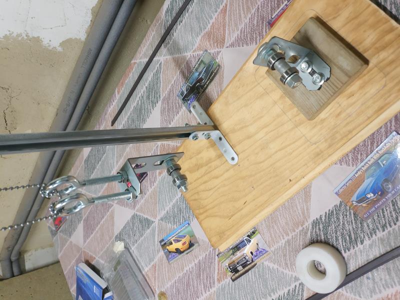
The accuracy of the scale is 0.1 gram. The variation in measurements can reach 5 grams. I think that the problem is the support on both sides, it must have too much friction and it does not get to focus since as it is set on a point it does not move from there and I do not know how to solve that, it comments on paper clip, but no I get to see that option, some image of some homemade gadget would be fine. The total weights if they are constant but separately never coincide is very frustrating. Rod 1 - 678,2gr 2- 679,2gr 3- 682,4gr 4- 682,6gr 5- 683.0gr 6- 684,1gr 7- 682,7gr 8- 681,2gr Until you get the repeatability of the weights consistent with your rod end weighing scale, there’s no need to try to weight balance the rod ends. Whatever you do, do not try to balance the rods based on the overall weights. That typically makes the end weights even more inconsistent. It’s not unusual for the rods themselves to have as much as a 5-6 gram variance at the ends when the scale readings are consistent so you’ll have to resolve that weight inconsistency problem before proceeding forward.
  Lorena, Texas (South of Waco) Lorena, Texas (South of Waco)
|
|
|
|
|
capelo
|
|
|
Group: Forum Members
Last Active: 5 Years Ago
Posts: 279,
Visits: 4.5K
|
capelo (3/8/2020)
I have done dry assembly of the rods with the pistons to measure the free space with the platform, then milling for a zero platform, these are the measurements, I would like your opinion on how much to mill. N°1- 0,044" N°2- 0,043" N°3- 0,044" N°4- 0,052" N°5- 0,045" N°6- 0,0425" N°7- 0,040" N°8- 0,046" Thanks for the comments, when reading dry assembly, act badly by not using some type of lubricant, now lubriciously more or will I have to polish the marks? about the measurements of the platforms any comments?
|
|
|
|
|
Ted
|
|
|
Group: Administrators
Last Active: 2 days ago
Posts: 7.5K,
Visits: 205.8K
|
capelo (3/8/2020)
I have done dry assembly of the rods with the pistons to measure the free space with the platform (deck), then milling for a zero platform (deck), these are the measurements, I would like your opinion on how much to mill. N°1- 0,044" N°2- 0,043" N°3- 0,044" N°4- 0,052" N°5- 0,045" N°6- 0,0425" N°7- 0,040" N°8- 0,046" With the #4 and #8 pistons being significantly deeper in their holes than the rest, I suspect you have connecting rod length and/or crankshaft stroke variance issues. Are all the connecting rods the same length? Is the stroke at all four rod journals the same? If not, then you can juggle the connecting rods within the various bores to get the piston to deck measurements closer to being equalized. Anytime the connecting rods and crankshafts are re-machined, the possibility that variances will be introduced where there were originally none is always increased. Once you get the measurements equalized to the point of being closer, then the decks can be machined to bring the pistons closer to the decks. If using composition head gaskets, then having the pistons level with the decks helps to maximize the compression ratio. A 'zero' deck is ideal in most instances wit h an iron headed Y.
Lorena, Texas (South of Waco)
|
|
|
|
|
capelo
|
|
|
Group: Forum Members
Last Active: 5 Years Ago
Posts: 279,
Visits: 4.5K
|
Ted (3/10/2020)
capelo (3/8/2020)
I have done dry assembly of the rods with the pistons to measure the free space with the platform (deck), then milling for a zero platform (deck), these are the measurements, I would like your opinion on how much to mill. N°1- 0,044" N°2- 0,043" N°3- 0,044" N°4- 0,052" N°5- 0,045" N°6- 0,0425" N°7- 0,040" N°8- 0,046" With the #4 and #8 pistons being significantly deeper in their holes than the rest, I suspect you have connecting rod length and/or crankshaft stroke variance issues. Are all the connecting rods the same length? Is the stroke at all four rod journals the same? If not, then you can juggle the connecting rods within the various bores to get the piston to deck measurements closer to being equalized. Anytime the connecting rods and crankshafts are re-machined, the possibility that variances will be introduced where there were originally none is always increased. Once you get the measurements equalized to the point of being closer, then the decks can be machined to bring the pistons closer to the decks. If using composition head gaskets, then having the pistons level with the decks helps to maximize the compression ratio. A 'zero' deck is ideal in most instances wit h an iron headed Y.
I bought the crankshaft and everything is correct, the four connecting rod race is the same, the difference is in the length of the rods. But fixing this now is not possible and would be very expensive, which comments on juggling the rods, how would you advise its placement for a more balanced measure when machining the covers ?. the head gasket will be the one of BEST Gasket. thanks
|
|
|
|
|
capelo
|
|
|
Group: Forum Members
Last Active: 5 Years Ago
Posts: 279,
Visits: 4.5K
|
 Ted (3/9/2020)
capelo (3/8/2020)
The accuracy of the scale is 0.1 gram. The variation in measurements can reach 5 grams. I think that the problem is the support on both sides, it must have too much friction and it does not get to focus since as it is set on a point it does not move from there and I do not know how to solve that, it comments on paper clip, but no I get to see that option, some image of some homemade gadget would be fine. The total weights if they are constant but separately never coincide is very frustrating. Rod 1 - 678,2gr 2- 679,2gr 3- 682,4gr 4- 682,6gr 5- 683.0gr 6- 684,1gr 7- 682,7gr 8- 681,2gr Until you get the repeatability of the weights consistent with your rod end weighing scale, there’s no need to try to weight balance the rod ends. Whatever you do, do not try to balance the rods based on the overall weights. That typically makes the end weights even more inconsistent. It’s not unusual for the rods themselves to have as much as a 5-6 gram variance at the ends when the scale readings are consistent so you’ll have to resolve that weight inconsistency problem before proceeding forward. I have already been able to solve the problem for a constant measurement with an error of 0.5gr, the problem was the friction in the supports, I have placed some bearings for the solution, now I can continue with this work. 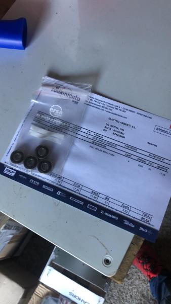
|
|
|
|
|
Ted
|
|
|
Group: Administrators
Last Active: 2 days ago
Posts: 7.5K,
Visits: 205.8K
|
capelo (3/10/2020)
I bought the crankshaft and everything is correct, the four connecting rod race is the same, the difference is in the length of the rods. But fixing this now is not possible and would be very expensive, which comments on juggling the rods, how would you advise its placement for a more balanced measure when machining the covers ?. the head gasket will be the one of BEST Gasket. thanks The block decks are typically high on their opposing ends and short on the other two. In redneck terms, the blocks are catty cornered or whopper-jawed. Now that you have some figures for your deck heights with all eight pistons, take measurements of those rod lengths and correlate them to the cylinders. What you essentially want are the short rods in the short cylinders and the long rods in the long cylinders. This is all assuming that both the crankshaft strokes and wrist pin locations (compression heights) are all the same to within one thousands of an inch. In going through some of my notes on block decking for the Y’s, they are pretty much equal on which corners are high and which are low. Half of the blocks are high on cylinders 1 & 8 and low on cylinders 4 & 5 while the other half are a mix of the decks being either whopper-jawed on the opposite corners or the decks simply being higher on or at the same ends of the block.
Lorena, Texas (South of Waco)
|
|
|
|
|
capelo
|
|
|
Group: Forum Members
Last Active: 5 Years Ago
Posts: 279,
Visits: 4.5K
|
Thanks for the help, I'm going to get to work on that, a question, can I somehow measure the block cover? I already did some. Check further and detect that in the threaded area for the fixing screws of the heads it is deformed outwards, between 0.001 and 0.002 ", and you can tell that sometimes I fixed the foot of the dial gauge on them, hence an erroneous measurement that I have already been able to check correctly on two cylinders with a variation of 0.004 ". I also checked with the highest and lowest connecting rods (4 and 7) in the same cylinder and it gives a difference between them of 0.004 ". I will continue working on this
|
|
|
|
|
capelo
|
|
|
Group: Forum Members
Last Active: 5 Years Ago
Posts: 279,
Visits: 4.5K
|
I have made new measurements and I have tried to compensate the heights of the pistons, I do not know if what I did is correct since it gave me a lot of headache, if someone confirms the thought I would be very grateful, these are the measurements:
P1-.0.042
P2-0.043
P3-0.043
P4-0.046
P5-0.043
P6-0.042
P7-0.042
P8-0.046
I have tested pistons in cylinder 7 (4-5-6-7-8) and pistons in cylinder 4 (1-2-3-4-7) with these results:
C7: P7-0.042
P6-0.0405
P8-0.043
P5-0.041
P4-0.046
C4: P4-0.047
P7-0.042
P2-0.046
P1-0.048
P3-0.046
And my configuration that I do not know if it is correct:
(1-2-3-7)
(5-4-8-6)
|
|
|
|
|
Ted
|
|
|
Group: Administrators
Last Active: 2 days ago
Posts: 7.5K,
Visits: 205.8K
|
capelo (3/12/2020)
I have made new measurements and I have tried to compensate the heights of the pistons, I do not know if what I did is correct since it gave me a lot of headache, if someone confirms the thought I would be very grateful, these are the measurementsThat’s quite a bit of wrist pin variance. Were those pistons all checked with the same connecting rod?capelo (3/12/2020)
Thanks for the help, I'm going to get to work on that, a question, can I somehow measure the block cover? I already did some.If by ‘block cover’ you mean deck, then measuring the decks at all four corners accurately takes some specific tools not available to the mainstream hobbyist.For a backyard way of doing this, just machine a steel bar or bushings the same diameter of the main holes without the bearings. If going the bushing route, then the internal hole size needs to fit a smaller diameter bar freely. The bar only needs to be long enough to fit into two journals at a time. With that bar in place between main journals, you can then use a depth micrometer to measure from the deck to the bar. Then add ½ the diameter of the bar to your measurement and you’ll have the deck height at the point you are measuring. I would measure from each side of the cylinder and record the measurements as such. Once you have all the measurements, you can then make a plan on how to square deck the block depending upon the wrist pins, rod lengths, and any variation that may occur in the crankshaft strokes.
Lorena, Texas (South of Waco)
|
|
|
|
|
capelo
|
|
|
Group: Forum Members
Last Active: 5 Years Ago
Posts: 279,
Visits: 4.5K
|
Ted (3/13/2020)
capelo (3/12/2020)
I have made new measurements and I have tried to compensate the heights of the pistons, I do not know if what I did is correct since it gave me a lot of headache, if someone confirms the thought I would be very grateful, these are the measurementsThat’s quite a bit of wrist pin variance. Were those pistons all checked with the same connecting rod?capelo (3/12/2020)
Thanks for the help, I'm going to get to work on that, a question, can I somehow measure the block cover? I already did some.If by ‘block cover’ you mean deck, then measuring the decks at all four corners accurately takes some specific tools not available to the mainstream hobbyist.For a backyard way of doing this, just machine a steel bar or bushings the same diameter of the main holes without the bearings. If going the bushing route, then the internal hole size needs to fit a smaller diameter bar freely. The bar only needs to be long enough to fit into two journals at a time. With that bar in place between main journals, you can then use a depth micrometer to measure from the deck to the bar. Then add ½ the diameter of the bar to your measurement and you’ll have the deck height at the point you are measuring. I would measure from each side of the cylinder and record the measurements as such. Once you have all the measurements, you can then make a plan on how to square deck the block depending upon the wrist pins, rod lengths, and any variation that may occur in the crankshaft strokes. Ted, you might have expected me wrong, what I did was test all the connecting rods on one side in the same cylinder with the same piston, plus one on the opposite side. So I did it in cylinder 7 and 4
|
|
|
|